Rigid-flex PCBs Manufacturing and Cost
2023-03-28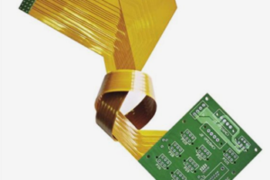
With flexibility and the ability to assemble in 3D, the demand for rigid-flexible PCBs is on the rise, and it can be said that the importance of rigid-flex PCBs in PCB manufacturing cannot be overstated.
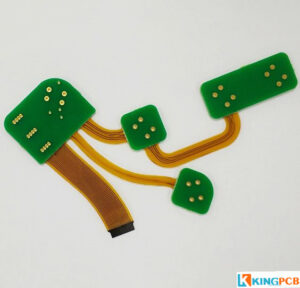
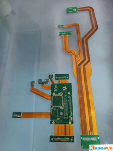
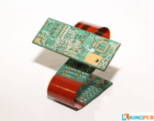
Rigid-flex PCBs connect rigid PCB materials to flexible materials. The result is bending only in certain places, making the board more rigid but still flexible. If you want signals to be transmitted between the rigid and flexible sections, you will need to design a rigid-flex PCB. In a rigid-flex design, the flexible part of the board resembles a typical flex circuit.
At the same time, the material of the rigid part is similar to that of a standard rigid PCB. Like standard PCBs, these rigid areas are usually made of glass fiber as the base material. Multilayer rigid-flex PCBs also include prepreg glass fibers as an intermediate substrate layer.
However, not all PCB manufacturers can meet the complex flexible printed circuit board manufacturing process. The following are some of the characteristics of rigid-flexible PCBs.
Features of rigid-flex PCBs
- Flexibility
- Lightweight
- Cost effective
- Save design and assembly process time
- Low noise and high reliability
- Resistant to high and low temperatures and fire
- Prevent electrostatic interference
Rigid-flex PCB manufacturing procedures
The rigid-flexible manufacturing process combines the manufacturing techniques of rigid and flexible boards. They are made by stacking rigid and flexible PCBs in layers. Components are assembled in the rigid area and interconnected to the adjacent rigid board through the flexible area. Layer-to-layer connections are then introduced through plated vias. Rigid-flexible manufacturing consists of the following steps:
- Material cutting
- Dry film coating
- Automatic optical inspection
- Browning
- Lamination
- X-Ray Inspection
- Drilling
- Electroplating
- Graphic Conversion
- Etching
- Screen Printing
- Exposure and Development
- Surface Finishing
- Depth Control Milling
- Electrical Testing
- Quality Control
- Packing
Rigid-flex PCB design rules considerations
Rigid-flex board in the design than the standard PCB design is much more complex, pay attention to a special place, especially the rigid-flexible transition area, alignment design, over-hole design, etc., are required to follow the corresponding design rules of the requirements:
Over the hole location
In the dynamic use of the situation, especially when the soft board is often bent, the soft board over-hole is required to avoid as far as possible, this over-hole is easy to be damaged by the fracture.
The design of the solder pads and vias
Solder pads and vias in line with the electrical requirements, win the maximum, the connection between the pad and the conductor using a smooth transition line, avoid right angles. Independent pads should be added disk toe to strengthen the support role.
Alignment design
In the flex zone (Flex) alignment design requirements are best to go rounded lines, rather than angled lines. The opposite of the hard board (Rigid) area recommendations. This can protect the flexible board part of the line in the bending is not easy to break. 4.
Lay copper design
For enhancing the flexibility of flexible bending of flexible board, laying copper or flat layer is best to use the mesh structure.
The distance between the drill hole and the copper skin
For the rigid-flexible combination area, the two most important distances must not be ignored. One is the hole to copper distance (Drill to Copper) described here, following the minimum standard of 10 mil. The other is the previously mentioned hole to the edge of the flexible board distance (Hole to Flex), generally recommended 50mil.
The design of the rigid-flexible area
The line should be a gentle transition, the direction of the line should be perpendicular to the direction of the bend. Wires should be evenly distributed throughout the bending area.
What material does rigid-flex PCBs choose?
Rigid-flex PCBs as the name suggests is a combination of rigid and flexible materials, including core, prepreg, copper foil, flexible laminates, cladding and bonding layers.
Flowless prepreg is one of the key components in rigid-flexible fabrication. This material prevents the epoxy from flowing into the flexible part of the PCB.
Flexible PCBs can be made of materials only a few microns thick and are commonly used in satellite and aerospace applications.
If you have questions about this, ask your PCB manufacturer for guidance on your PCB lamination and design rules.
How to reduce assembly cost with rigid-flexible PCBs?
The main factors affecting the cost of PCB is the material, size, number of layers, surface treatment and vias, of course, there are other factors, depending on the requirements of the PCB design.
Material selection
The cost of different PCB material selection is also different. the most commonly used material for PCB is FR-4, for different application scenarios, the factors affecting the choice of material may be the following.
- Temperature requirements
- Heat transfer
- Signal performance
- Mechanical properties
Size
The size of a PCB will generally be determined by the number of circuits required for the respective device. For small devices such as cell phones, wearable devices, etc. require relatively few components, while the size of the PCB in larger devices will be larger.
Number of layers
Another important factor that affects the price of circuit boards is the number of layers. Obviously, the complexity of production of multilayer circuit boards (greater than two layers) also leads to an increase in its cost. Overall, each additional two layers may lead to an increase in cost of 30% to 40%, although the specific circumstances need to be evaluated.
Surface treatment
PCB production on the need to consider a factor is the surface treatment technology. The most common surface treatment is HASL, which provides good solderability, for higher requirements of the PCB, ENIG will be a good choice, but the cost is also relatively higher.
Vias
The size and number of vias is also one of the important factors affecting the cost of PCB production. More vias means more work. The general size of the via diameter is not less than 0.3mm, less than this value may require the use of light drilling equipment. Different types of vias require different technologies for HDI PCBs involving vias such as blind vias, micro vias and buried vias, which have certain requirements for the PCB manufacturer's manufacturing capabilities.
Minimum track space
In order to make the effective transmission of current on the PCB, the board must be designed with sufficient alignment width, the alignment width to a certain extent determines the carrying capacity of the board.
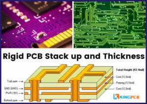
PCB thickness and aspect ratio
The standard thickness of the PCB is 1.6mm (0.063 inches). In general, the cost of thicker circuit boards will be more expensive. Thicker boards also have a larger aspect ratio, and it can be significantly more expensive. For your board thickness manufacturing requirements, consult the PCB manufacturer for more information.
Other custom requirements
Unique circuit board designs often require additional processes, such as
- The board is designed with many vias beyond the standard specifications
- Combining multiple designs on a single board
- Additional solder resist layer gaps and thicknesses, etc.
Using rigid flexible PCB in your project can save some costs:
- Direct cost: reduced bill of materials(BOM) and inventory. For multiple interconnected rigid PCBs, flexible PCBs can replace wiring harnesses and eliminate the requirement for connectors, providing direct cost savings.
- Overhead costs: Because rigid flexible PCBs do not involve harness assembly, can reduce assembly costs and improve reliability.
How to minimize the manufacturing cost of rigid-flexible PCBs?
Keep the number of layers as few as possible
Reducing the number of layers can reduce the amount of prepreg for PCB manufacturing. The same fewer layers also simplify the PCB manufacturing process, thus reducing the total PCB manufacturing cost
Rigid laminates are used to achieve overall thickness
It is suggest to use rigid laminates to achieve a specific total thickness, which is less costly than non-flow prepreg.
Make sure the flexible part ends at the rigid part
If the PCB design requires one or more flexible arms of the flexible PCB to end in a flexible cable, additional mechanical support(flexible stiffeners). Because flexible connections do not have thickness or stiffness, having the flexible arm end up in the rigid part reduces the overall cost of a rigid-flexible PCB.
To avoid high costs associated with unique PCB design requirements, calculate potential items that may be present in your design prior to production and communicate carefully with your PCB manufacturer to avoid doubt.
Applications of rigid-flex PCB
- Industrial use: industrial, military, medical
- Automotive: automotive components, in-car video systems, audio systems, radar imaging systems, satellite navigation, temperature sensors, etc.
- Consumer electronics: folding cell phones, video modules, keypads, RF templates, etc.
KingPCB's customer support team can help you find the best material and structure for your flexible or rigid-flex PCB. Visit our contact page to send us a message online.
Summarize
The earlier you consult the PCB manufacturer in the planning stage, the better your PCB will be. Optimizing the PCB for your final product can save you money during system assembly.
KingPCB's flexible PCB services include Flexible PCB prototype, Rigid Flexible PCB, and Flexible HDI PCB. Contact us now for the latest quote on your PCB!
