Blind & Buried vias PCB Assembly
2022-08-31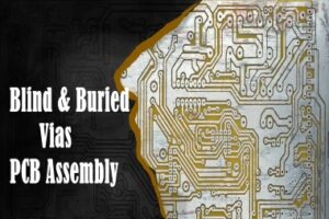
In a printed circuit board (PCB), the various chips and components contained therein conduct signals for different functions according to the design requirements. And most of the signals on a printed circuit board are conducted via vias on the board. For high-precision, multi-layer PCBs, the flexible design of different via holes helps to create connections between the multiple layers of the PCB.
In this article we focus on the role of blind and buried vias.
What is Via?
Essentially, vias provide the conduction path for electrical signals to pass from one circuit layer to another. Via holes are plated through-holes in a PCB that can be used to route traces from the surface of the board to the inner and outer layers. Vias are essential in multilayer boards as they create the path for the flow of current between the layers.
Main Types of Vias-Blinds and Buried Vias
There are two main types of vias, depending on their location in the PCB layers - blind and buried vias.
Blind Via Holes
The application of blind vias has arisen in order to increase the space utilisation of the PCB circuit layers. Blind Via Holes are plated holes that connect the outermost circuit of the PCB to the adjacent inner layer and are called Blind Via because the opposite side is not visible.
Buried Holes
It are used to connect any circuit layer within a PCB but are not routed to the outer layer. As the name implies, the buried hole is hidden underneath the board without affecting the surface circuitry and components. Because of the greater demands placed on PCB assembly manufacturers, this process is usually only used for high-density (HDI) circuit boards to allow for better power transmission and to increase the space available for other circuit layers.
Blind vias in PCB assembly
Four types of blind holes are described here
- Photo-defined blind holes. Created by laminating a piece of photosensitive resin onto a core. These through-holes are typically used to create BGA packages.
- Sequentially laminated blind vias. Created by handling a thin piece of laminate. The laminate is drilled, plated and etched. The other side is left as a solid copper sheet.
- Controlled depth blind holes. Created like a through-hole. The drill bit can only penetrate the PCB in a certain way.
- Laser drilled blind holes. Created after all layers in the PCB have been laminated and before the outer layer has been plated and etched. By using a CO₂ laser or an Eximer laser, the outer copper layer is ablated.
Advantages of blind vias
Blind vias help to reduce parasitic capacitance. This is achieved by shortening the length of the through-holes and reducing their diameter. Blind vias are therefore a good way to connect signal lines operating above 4.8 Gb/s.
To Summarize
The main advantages offered by blind and buried vias include
- Meeting the density requirements and constraints of lines and pads in a design without increasing the total number of layers or board size
- Save space and meet extremely tight design tolerances.
- Manage hole-to-pad ratios and limit opportunities for breakthrough.
- Of concern is that they increase the cost of manufacturing the board as well as the cost of testing. However, between the two, buried holes are less costly.
It is important to choose the right electronics contract manufacturing partner with the necessary experience in blind and buried vias. KingPCB has over 10 years’ experience in electronics manufacturing, including PCB manufacturing and PCBA assembly, providing high precision PCB through-hole manufacturing.
Please feel free to contact us by email with any questions, getting an latest quote starts here!
