Standard Tests in PCB&PCBA
2022-09-23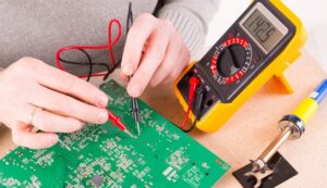
What types of standard tests are available in PCBs/PCBAs?
The inspection of PCBs & PCBAs is an essential step in order to ensure product quality. Today the PCB manufacturing industry and associated manufacturers have established a wide range of test methods and evaluation techniques that allow for better inspection of components that may have failed. Seven common inspection methods are as follows.
- Visual inspection, where the operator uses a magnifying glass or microscope to check if the board passes. Visual inspection is the most traditional method of inspection, but due to the increase in PCB production and the continuous development of high-precision PCBs, visual inspection has become unfeasible and needs to be instrumented.
- ICT (in-circuit tester) is a modern electronic enterprise necessary PCBA (printed circuit board assembly) test equipment, it can find 98% of the fault. The ICT Test is mainly a test probe that touches the test points from the PCB layout to detect open circuits, short circuits, and the soldering of all parts of the PCBA. With simple operation and fast and accurate fault location, it can significantly improve production efficiency and reduce maintenance costs.
- FICT, also known as Flying probe testing, replaces the pin bed with probes, using multiple motor-driven, fast-moving electrical probes to make contact with the pins of the device and make electrical measurements. A typical ICT may take 30 seconds to test a UUT, whereas a FICT may take 8-10 minutes.
- FCT (functional circuit test) generally refers specifically to testing after the PCBA has been powered up. This type of test is always carried out at the end of the manufacturing circuit board programme, using a functional tester to check that the finished PCB meets specifications. The tester is usually connected to the PCB via its test probe points or edge connectors and tested to prove that the PCB functions according to the design specifications. The test process is fully automated by computer and the results are reported without human intervention, ensuring efficiency and compliance
- BSTT (boundary-scan test technology) is widely used as a method of testing integrated circuit boards. The cell is placed in the leads from the silicon to the external pins and the status of the input and output pins of the IC chip is tested, as well as the internal operation of the chip and the lead level for the break and short faults.
The main difference in this type of test is that it is possible to check for circuit or wire faults simply by running a computer program.
It is very suitable where reliability is important and troubleshooting time is short.
- AOI (automated optical inspection) is a device based on optical principles to detect common defects encountered in soldering production. The defects are displayed/marked out for repair by the display or automatic signs
- AXI (automatic X-ray inspection) X-rays are non-destructive and have different penetration rates for different substances. AXI technology is now widely used for product inspection in industries such as lithium batteries, semiconductors, integrated circuits, and electronics manufacturing.

Why is it necessary for PCB Testing?
- Error identification: Helps to identify possible functional, manufacturability, or PCB design and PCB layout problems in the PCB, so that designers can make timely adjustments
- Time saving: PCB testing at an early stage helps to save time, and complete and thorough testing helps to quickly identify the cause of problems and shorten product delivery lead times
- Cost reduction: testing products in small assemblies prevents the production of defective products and ensures that problems occur before they are put into production.
- Reduced rework rates: helps to reduce the number of products that do not meet performance standards, increasing customer satisfaction and improving the company's reputation.
