SMT PCB Assembly - Surface Mounted Vs Through Hole Technology
2019-12-09Over the years, we have seen the evolution of Printed Circuit Boards, an evolution that leads to the SMT PCB Assembly. They have become an important part of modern-day electronics. Initially, the circuit boards were of big sizes, however, contemporary techniques made it possible for the PCBs to become small in size and weight.
Today, we use two main techniques for placing the components on the Printed Circuit board. First, is the Through-Hole Mounting and second is the Surface Mount Technology. Both these techniques offer have their pros and cons. In the course of this article, we will discuss both these techniques in detail.
The objective is to make you understand the different types of PCB technology.
Table of Content
- What is Through-Hole Technology?
- Why people Still Use THT?
- Through-Hole Technology- Cost Efficient
- Radial Vs Axial Leads
- What is Surface Mounted Technology?
- SMT PCB Assembly: Design Considerations
- Advantages and Disadvantages
- Comparison of Characteristics
What is Through-Hole Technology?
In the 1950’s, the PCB manufacturer was able to produce PCBs’ with one-sided tracks printed on the board. To insert the lead of components, drills were brought into action. The manufacturer incorporated the drills, thus allowing the placement of the components on the empty side of the board. The soldering mask was used on the tracked side of the board.
The development of technology had a direct impact on the PCB production technique. Since the introduction of the second-generation computers, PCB manufacturer has been using Through-hole technology for PCB board fabrication.
In through-hole technology, it is possible to trace both sides of the board along with having tracks on the inner layers of the Printed Circuit boards. In addition, the plated-through hole technology became a reality.
With PTH, manufacturers were able to connect to tracks on the inner layer of the Printed Circuit Board.
Why people Still Use THT
Yes, technologies that are more sophisticated have come into existence, yet we see a large number of manufacturers using THT for Printed Circuit Boards. They have a valid reason for using it. For instance, it is possible to use any hobbyist for THT PCB assembly with soldering iron. You can even assemble a bunch of PCB without additional worry. The reason being, the space between holes that holds the components.
Generally, PCB board fabrication manufacturer use a minimum spacing of 0.100’’. By spacing, we mean the distance between the one hole’s center to its immediate next hole. Even the DIP processors use this kind of spacing. Due to this generous amount, it is possible, one can effortlessly hand-solder the Printed Circuit Board. In addition, the spacing eliminates the chances of unintentionally making links between two adjacent components or between the pins on a single component.
The lack of error not only increases the board's robustness but at the same time, it significantly decreases troubleshoot and rework that might be required after the board assembling. The through-hole technologies usefulness does not end here. On the contrary, you can effectively use them in a more professional environment.
A good idea is to use them during the prototype stage of the project. Using the through-hole component during prototype temporarily allows it to, quickly assemble the PCB to ensure that the design would work.
Once they ensure that the board functions correctly, they can turn towards SMT PCB Assembly, a more advance technique. These steps help save MCPCB manufacturers as well as other PCB manufacturers upfront cost of a project. Using THT for prototyping is highly effective for firms that have subcontracting a bunch of printed circuit boards to third party manufacturers.
Through-Hole Technology- Cost Efficient
Through-Hole Technology is cost-efficient. Manufacturers tend to save hundreds of dollars as they do not have to create new stencils for every revision of the Printed Circuit Board. The THT is perhaps the best choice for the design that has to undergo multiple spins. You do not have to buy the accompanying reels of SMT or to set up pick and place equipment before Printed Circuit Board’s final Configuration.
It is possible to perform testing manually; in addition, you can do in-house testing, provided the number of Printed Circuit Board is small. The ability to perform testing either manually or in-house reduces the expenses associated with the set-up and fixtures.
To, further reduce the cost, Through Hole technology makes it possible for you to use the in-lead solder. Tin-lead is an expensive surface material. Similarly, with this technology, the HASL (Non-Planarity of Hit-Air Solder Leveling) is not a problem. You can effortlessly make the placement of the components on the fine pitch.
Radial Vs Axial Leads
The through-hole mounting components are further categorized into two, first the Axial and second the Radial. Both these techniques have a little difference in them. If the PCB Manufacture plans to place the leads on both end sides of the components then axial is the best choice.
For placing the leads on only one end side of the components, the manufacturer should opt for the radial component technique.
What is Surface Mounted Technology?
The evolution of through-hole technology led to the Surface Mount Technology. In 1960, manufacturer some manufacturer shifted to the SMT technology, and by the mid-80, almost every manufacturer used Surface mounted technology.
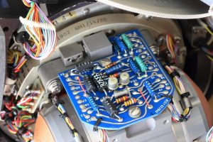
Initially, the technology was famous as Planar mounting. The components of the SMT had Surface Mount Packages. There are leads around and beneath the components. The major difference between SMT and the THT is the lack of hole drilling. You do not need to drill holes into the Printed Circuit board in order to form a connection between the components and the tracks of the PCB.
With the help of the component leads, it is possible to make direct contact with the PADs along with the components. To place the solder on the empty PADs, you will need stencils. After that, a Pick and Place machine comes into action. Using this machine, you can easily place the components on the solder paste covered PADs.
After the placement of all components, the Printed circuit board along with the placed components will go through a reflow oven. In some cases, the manufacturers use the Vapor in order to solder the Printed Circuit Boards.
Why use Surface Mounted Technology?
Despite all the above justification about the Through-hole technology it not able to match the benefits offered by SMT.
Among the numerous reasons, the most obvious is the ability to achieve a far greater level of density with SMT. Likewise, it is possible to offer high processing power will retaining the size and the small of the overall PCBA.
The PCBA factory owners truly understand the power of surface mounted technology, thus they incorporate it for almost every PCB. In addition, the PCBA factory owners need to meet the market demands i.e. decreased device while increased efficiency.
This is not possible with through-hole technology, thus the SMT PCB Assembly becomes necessary. If you are still doubtful, let us take an example. To approximate the power of 64-pin QFP or BGA-single surface-mounted processor, you will need several 16-pins or 14-pin measuring around 0.8” x 0.35” dual-in-line processors.
You would also need extra space for the interconnections on the Printed Circuit Boards. However, using the Surface mounted technology eliminates the need to have an individual plated TH for every THT component lead. You will be using a rather a surface pad that will mimic the functionality of several plated through-holes.
To, further enhance the power and decrease the size of the Printed Circuit board, you can easily drill small vias. Since the vias drilling is an option, thus you can drill them directly beneath the Surface mounted technology component leads, thus allowing the interconnection of the Z-axis.
The connection can instigate from the walls of vias to other layers of the printed Circuit Board. It is possible to form interconnections within or to the next to the device’s own footprint. This entire process does save up a lot of space. Next, you can place additional components around the space available around the Surface Mounted Technology.
The two main reasons SMT PCB Assembly manufacturers are able to achieve higher densities are smaller footprint sizes and additional space. When you remove the drilling components, you automatically acquire extra space. Another major advantage is to mount the components on all sides of Print Circuit
SMT does offer numerous benefits, but you also need to pay close attention to the designing and production process to yield results. It is important to consider the material mechanical characteristics, and material for finish during the design of SMT Printed Circuit Boards. If a problem occurs with these factors, it can lead to some serious problems.
SMT PCB Assembly: Design Considerations
As we told you above, you really need to pay close attention to the material and surface finish of the SMT PCBs. If your SMT PCB were incorporating components with pin pitches 0.05”, or less, we would never recommend you to use leaded solder. The reason we object is after cooling down in a non-planner state, the leaded solder used in HASL tends to pool up at the Pads one end.
For effective results and to avoid positioning problems during the automated placement, it is imperative that the leads sit flat. A flat component lead will ensure that there is no problem with RoHS compliance. A good idea is to use material offering planar finish. Some examples include Immersion Tin, Immersion Silver and Electro-less Nickel Immersion Gold, etc.
Since SMT uses a lead –free surface finish, therefore it generally requires high soldering temperature in comparison to that of the through-hole boards. Therefore, you need to make sure that you use the right base laminate. Ensure that you choose a material that can stand up to high soldering temperature. IPC-41010D/126 standard meeting materials
- Td 340C
- Tg 170C among others
Since the soldering of the 2-sided surface mounted technology board requires several thermal cycling, thus you need one of these materials. As these materials have the ability to withstand not one, but several thermal cycling shocks.
To ensure the smooth processing of SMT PCB Assembly, every external layer should have one set of fiducial pads. This will help the pick and place machinery to find the placement of the components.
Advantages and Disadvantages
Both types of printed circuit board technologies offer advantages as well as disadvantages.
Through-Hole Technology Advantages
- Due to a strong connection between the Printed Circuit Board and the component, THT PCB are more reliable in comparison to the SMT PCB Assembly boards.
- THT has the ability to withstand a lot of stress and fast acceleration on the PCB.
- THT components are easier to remove.
- They are easier to test and excellent to use as a prototype.
Through-Hole Technology Disadvantages
- The components of Through-Hole technology take up a lot of space on the Printed Circuit Board.
- You will have to manually, replace most of the through-hole mounted components.
Surface Mounted Technology Advantages
- Through-hole components are expensive in comparison to the Surface mounted components.
- SMT components are smaller than the THT, thus they take up less space on the circuit board.
- The production time is less due to the usage of Pick and Place equipment.
- It is possible to use both sides of the Printed Circuit Board.
Surface Mounted Technology Disadvantages
- It is not a wise idea to use SMT for prototyping as it will cost you a lot.
- Some believe that SMT is not suitable for applications that require high-power
Characteristics Comparison
Through Hole Technology The Surface Mounted Technology
| It is pretty common to have HASL, non-planar finish. | Use material that offers Planar finish such as OSP, Immersion Silver, ENIG |
| It is rare for a THT PCB to have a two-sided assembly | SMT offers great ease of having two-sided component placement |
| For component lead placement, you will need holes. | No holes are needed, in fact, the Components are mounted onto the surface pads |
| You will have to manually assemble it | Automated assembly. |
| 0.100” is the minimum distance between every Component lead | 0.0157” or the 0.0197” is the Component lead spacing |
| Soldering automated Or manual | Usually, Soldering is automated. |
| Vias in pads not possible. | Vias in pads possible |
| You do not need stencils | You do need Stencil |
| Through-hole test points. | SMT or Through-hole test points |
| (130C Tg)- Standard Temperature laminate | (170C Tg)-High Tempeature laminate |
| Do not need the fiducial pads for component placement. | Do need the fiducial pads automated pick-and-place equipment. |
| Moderate twist and warp endurable | Twist and Warp important for assembly |
| Rework is easy | Reworking can be difficult at times |
| Large PCB Foot Print | Small PCB Foot Print |
Summary
SMT PCB Assembly and Through-hole PCB assembly offer different advantages and disadvantages. Where a Surface Mounted Technology can offer the high processing power, the through-hole technology offers robustness. With an SMT, it is possible to use both sides of the Printed Circuit Board, however, this concept is rare in the THT.
Choosing the type of technology for your printed circuit board mainly rely on your requirement. If your objective is to incorporate the PCB into electronics that will be working in extreme environments, THT should be your choice. Likewise, if the idea is to use in modern-day electronics that are small in size, we would recommend you go with SMT.
Regardless of the type of technology you use, it is imperative to select the best manufacturer on the market. We can assure you that you will not find a better one than KingPCB.
KingPCB has years of experience in developing SMT PCBs as well as THT PCBs. They are capable of handling orders of all sizes. They will guide you in every possible way to ensure that you make the best decision.
