Guide on PCB Board Fabrication
2019-12-01PCB Board Fabrication - Full Guidance
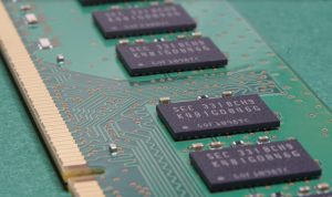
PCB Board Fabrication process requires proper research and indebt analysis. After all, printed circuit boards are the backbone of modern technology, thus they need to be of the highest quality. Of course, excellence comes with experience; however, you do need to pay heed to some factors in order to generate effective results.
In case you are wondering how to become an outclass PCB manufacturer, you have come to the right place. In the course of this article, we will provide you a complete guide on printed circuit board fabrication.
Table of Content
- What is PCB Board Fabrication?
- Why having a Proper Manufacturing Process is important.
- General Tips on Manufacturing Process
- Summary
What is Printed Circuit Board Fabrication?
All modern electronics rely on a small circuit board for effective and efficient performance. A PCB Board Fabrication is the assembly process of this particular circuit board. To ensure that these boards are compatible with modern electronics, the PCB manufacturer tends to use a specific pattern for the PCB layering.
There are companies that solely design and develop printed circuit boards; however, you might come across the manufacturer offer the facility of developing the electronics of the respective PCBs. There are different ways of fabricating the electronic goods, you can either reach out to third-party specialists of you can fabricate in-house. In addition, there are several companies that operate in the grey area. You just need to be sure before you decide on a PCB manufacturer.
Among several companies, we have KingPCB. They have been around for years and thus they excel in designing and developing outclass printed circuit boards. They can either supply design for the PCB or develop a PCB according to your requirements.
All you would have to do is provide the information regarding the functionality of the printed circuit board and the environment it will be working in. The rest, KingPCB will do effortlessly. Regardless, the type of printed circuit board you are looking for, they deliver quality.
KingPCB is an excellent MCPCB manufacturer, they are also famous for being an outstanding SMT PCB assembly manufacturer. So, you can rely on them for all types of printed circuit boards.
Why having a Proper Manufacturing Process is important.
For a product to be robust and generate effective results, it needs to have the right base. A good product is possible only if the manufacturing process is error-free. For something as important as a printed circuit board, it is imperative to choose a company that offers high-quality PCB Board Fabrication process.
A well-rehearsed and error-free manufacturing process will ensure that the printed circuit boards have minimal or zero errors. The holes will be properly drilled, the base would be of good material and soldering would be of the highest quality as well.
In addition, the manufacturer would use the latest techniques and equipment to produce robust and effective printed circuit boards. Only a good circuit board will boost the performance of the electronics. It will also increase its self-life, thus enhancing the brand image of the electronics company.
Read more about: Best PCB assembly manufacturer – Few Tips
General Tips on PCB Fabrication
Nodes accessibility
There is a high probability that you might have to resolve an issue in your Printed Circuit board. In order to do so, you would have to measure signals inside the PCB. For signal measurement, you will need access to the nodes. After all, circuit troubleshooting takes place via these nodes.
Make sure that all the important nodes of your printed circuit board are accessible. If you are hiring a third party PCB Board Fabrication company, ensure that they provide the facility of easily accessing the nodes required for troubleshooting. In addition, the manufacturer needs to test the nodes before rolling out the final product.
A manufacturer can use several ways to test, however, the most popular one is the forming loops that are excellent for testing probes with hooks.
Use same orientation throughout the PCB
The same orientation decreases soldering mistakes as well as makes component inspection easy. Therefore, it is good practice to place components with the same orientation. For example, a standard component pin numbering starts with pin#1 in the upper left corner. Just ensure that all the components pin placement is the same.
The right spacing
Once you have incorporated the node's accessibility into the design, the next thing that you need to focus on is the right spacing of the components. To ensure the longevity and robustness of a Printed Circuit board, it is imperative for the manufacturer to use the right spacing.
You might be tempted to pack all the components close to each other as this will not only decrease the size of the Printed Circuit board, but it will also reduce the weight. Nonetheless, you need to realize that it is important to leave space for the routing of wires. Ensure that there is enough space for the wire to move between the components.
The amount of space is greatly dependent on the number of component pins. In addition to making the wiring easy, the right spacing will make soldering easier and it will facilitate auto-routing as well.
Exchanging wiring directions Between Layers
On a circuit board, we often see wires crossing each other. Of course, experience ensures that the wires generate the desired results. To ensure the effective performance of the wires, you need to exchange wiring directions between layers.
A good practice is to have vertical traces on one side and horizontal traces on the other side. In case, you have multiple layers, you should go with alternating between directions.
Match the component sizes
To eradicate component size errors, and to ensure that there is no error in the datasheet, you need to ensure that the components’ sizes match. Instead of finding out later that the components are of different sizes, you should print the layout.
A printed layout will help you resolve if any problem might occur in the future. Take the printed layout and place every component on its respective place on the layout. You now will have a clear idea about component sizes.
Width of Line Selection
A good printed circuit board is also a good heat dissipation. However, not all circuit boards have this capability, therefore you need to ensure that your PCB Board Fabrication manufacturer is experienced enough to choose width of the lines according to the current.
If you go for a larger width, it will reduce resistance and in return, the head due to dissipation is reduced. You need to first estimate the current that will be flowing through these lines and then decide on the width size.
There are several online calculators that will help you decide the width size. So, you really don’t have to put in a lot of effort. Just ensure that the power lines are wider as major current flows through these wires.
90-degree angles with traces
As we mentioned above, having a constant width of wiring is important, but with sharp right angles, this can be extremely difficult. 90-degree angles with traces can be of concern especially when the difference is narrow.
A good PCB manufacturer understands that problem and thus, they will prefer using a 45-degree bend instead of 90 degrees.
Layout vs. Schematic comparison
An experienced Printed Circuit Board would ensure that there is matching between the schematic and the layout of the board. In order to do so, they use high-end and effective software. These software will generate effective results.
Consider Spots of heat
The heat has an adverse effect on the circuits. If you do not dissipate the heat, your circuit performance will decrease drastically. Excessive heat might also damage the circuit board permanently. Therefore, heat management is important.
You need to consider the component that consumes more power and how to dissipate their heat. A parameter called “Thermal Resistance” monitors temperature increase per watt of power under different situations.
For example, there is a copper area with x by y mm underneath the IC. You will need to incorporate heat sinks or even fan in order to dissipate heat to bring down the IC temperature. You should also isolate the critical parts of the board from the heat sources.
An effective Ground Plane is important
An effective printed board has everything with the same orientation and spacing. So, this means that the voltage should also remain the same in the Printed Circuit Board. This is extremely important, especially in the analog circuits.
There will be a voltage drop in case you trying to use traces to route the ground signal. The resistances created by the routes will lead to the voltage drop. The voltage drop tends to make different grounds in the Printed Circuit Board.
To avoid this, a good idea is to create a ground panel. You can either have a large area of copper or you can reserve a layer of the printed circuit board for the panel. A layer would ensure that components connect directly to the ground through vias.
If you have a complete copper panel, it will dissipate the heat quickly. However, there can be an adverse effect i.e. soldering the panels would be difficult. Nonetheless, it is possible to avoid this by making thin traces.
Keep Analog and Digital Grounds Separate
To ensure that there is no noise, it is a good idea to keep the digital and analog grounds separate. Current and voltage spiking from the digital circuits leads to the generation of noises in the analog circuits, thus having an adverse effect on its performance.
You can avoid all this by having separate grounds, but then you might have to tie them at some point. So, we suggest you put them together at the end of the supply path. This will serve your purpose as well as avoid interferences. There are other techniques available; however, manufacturer has generally preferred this particular one.
Place Bypass Capacitors
Incorporating bypass capacitors offer a number of benefits. These capacitors have the ability to filter the AC components of the power supply. In addition, there is a reduction in unwanted AC signals such as ripples, noise, etc.
The reduction takes place because the AC fluctuations are bypassed to the ground. So, whatever voltage you want to filter, simply connect the capacitor between it and the ground. For starters, you should go with the Powe inlet of your Printed Circuit Boards as a place for the capacitors.
The wires connected to the power supply often connect a lot of RF signals and they are long as well. If you want other places to place the capacitors, we would recommend incorporating them close to the ICs. Placing the capacitors close to the ground and power pins will reduce the noise present inside the Printed Circuit Board.
The AC components frequencies have a direct impact on the values of the capacitors. Since every capacitor has its own resistance and Equivalent Series Inductance, thus it has its own response to the frequencies. The ESL is tuned to a wide range of frequencies.
For instance, you will need a large capacitors in order to filter low frequencies. Likewise, for mid-range frequencies, you will need a capacitor of 0.1-1 µF. You can go with 1-10µF for low fluctuations and for high frequency, a good idea is to use 0.001-0.1µF capacitors.
Of course, one capacitor is not fit for removing different frequencies. So, a good idea is to use a combination of bypass capacitors. Use 10 µF - 100 µF capacitors for buffering for chips that drive a large volume of current.Manufacturers also use ceramic capacitors mainly because of their size and price. However, not all app capacitor values allow the usage of monolithic ceramic capacitors.
Silk Layer
MCPCB manufacturer uses standard practice of silk layering. The practice makes it extremely useful for labeling. With labeling, you will not only label your components, but it is possible to add information such as the author or the revision number of the circuit board.
Manufacturer specification
\
You will come across several manufacturers; however, every manufacturer comes with its limitation and specification. Some of these specifications include the component spacing, minimum trace width, number of layers, minimum weight and much more.
Before you start on your design, it is imperative to find a manufacturer that can meet with all your Printed Circuit Board needs. Do mention your requirements regarding the material’s grade of the Printed Circuit Board.
The grades range from FR-1 to FR-5. At KingPCB, they generally use FR-4; however, in the case of high-volume consumer applications they recommend FR-2. Nonetheless, the decision of using the grade type mainly depends on the client. After all the type of grade material will have a direct effect on the circuit board’s strength, moisture absorption, durability, and Flame Resistance.
Summary
An experienced PCB Board Fabrication company would understand that a well-designed PCB is perhaps the best. They would know that to deliver quality, they need to have quality at the base. The production system of the Printed Circuit Board should meet the highest possible standards. Of course, with so many PCB manufacturers out there, you will have to choose wisely.
Every company does claim to be the leading MCPCB manufacturer or SMT PCB assembly firm, but they will not deliver what they promise. On the contrary, KingPCB delivers high quality printed circuit board.
They use modern techniques to develop sophisticated Printed Circuit Boards. Their circuit boards are robust and they add value to consumer electronics. They incorporate the right layering technique, dedicate a special layer or large copper area to avoid multiple grounds and incorporate capacitors to dissipate heat.
They will also test the nodes and the spacing of the wires to ensure Printed Circuit Boards run effortlessly in the future. After all, the objective is to deliver high-quality PCBs to the clients within their budget and time-frame.
