FAQ of Flexible PCB
2022-11-08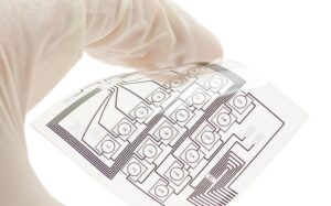
Flexible PCBs are a great innovation in the field of printed circuit boards. Flexible circuit boards are made of polyimide or polyester film as the substrate.
They are suitable for different electronic applications with their excellent flexibility. It has the characteristics of high wiring density, light weight, thin thickness and good bendability.
However, you may find that there may be some problems when using flexible circuit boards.
Why is there a problem with flexible printed circuit boards?
Because flexible PCBs are designed and manufactured for special applications, the cost of starting circuit design, wiring and photographic backing is higher.
In most cases, flex PCB problems occur because designers are used to designing rigid circuit boards, so they design flex PCBs based on the same principles. Of course, flexible circuit boards are not rigid circuit boards, they need their own flexible design.
What are the common flexible circuit board problems?
Stacking traces
It is important to ensure that copper stays on the neutral axis of the bend. When traces on either side of a dielectric stack overlap each other, the traces on the outside of the bend radius will usually break when the circuit is bent if the traces on opposite sides are perfectly aligned.
The farther the tension moves these traces away from the neutral axis of the folded region, the greater the likelihood of breakage.
By designing this area as a conductive layer, you can sidestep this problem.
Stress points in the conductor
At the bottom of the pads or sharp corners of the board with sharp bonding points, this situation does not apply to flexible boards but rigid boards. Because whenever the user bends the area where the stress point is located, there may be fractures or delamination.
Spacing between solder pads
It is important to ensure that the flexible circuit board you design has more space between each pad and its adjacent conductive traces to account for larger overlay openings. If the distance is too short, the result may lead to a short circuit between the connector pads and pins.
Solder joints too close to the bend point
Solder joints are the points where the solder is bonded to the copper traces. Due to the addition of solder, they are harder than the rest of the copper traces. In flexible boards, if the solder joints are too close to the bend point location will likely lead to pad breakage or loss of lamination, resulting in board damage.
Solder resist/overlay openings are not wide enough
The shape of the flex circuit may change somewhat during the manufacturing process. There are many complex processes to consider when designing a custom flex circuit, so it is important to make sure the openings in the overlay are wide enough.
How can I avoid problems?
To avoid problems with flexible circuit boards, it is important to get to the root of the problem - the design
Explore KingPCB's Flex PCB Services
If you need flexible circuit boards, rigid circuit boards or flexible-rigid combination boards, KingPCB is your reliable choice. We are one of the leading PCB manufacturers in the printed circuit board industry looking for the best design and manufacturing.
For more information and quotes on flexible circuit boards, contact us today!
