Beware of These 8 PCB Layout Pitfalls
2023-02-27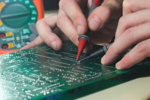
A printed circuit board layout consists of a number of copper traces and circuits that help establish connections between the components. How a PCB design and manufacturing occur largely determines how it will perform in the final product.
However, with the development of electronic technology, the circuit board is gradually in the direction of miniaturization and more precise development, so the layout will become more and more difficult and complex.
When designing PCBs, some layout problems can be costly and cause defects in the product, so they should be avoided whenever possible. Also, make sure you have a test strategy and involve your PCB suppliers early in the process to avoid design and manufacturing incompatibilities.
PCB layout traps
1. Plating holes/gaps
The holes and gaps in electroplating are caused by the imperfect deposition process. In the deposition process, if material contamination occurs, or contains bubbles, copper catalysis is insufficient, through hole cleaning is insufficient or rough drilling may cause electroplating hole problems.
Electroplating holes prevent current from flowing through the holes to the other side of the circuit board, causing the device to fail to operate properly.
2. Silver shavings
The solder shield or thin wedges of copper produced during etching, called silver chips, can affect the PCB's function:
- When long, thin layers of copper or solder resistance separate before they are fully dissolved in the chemical bath, silver shavings are created, which may attach to another board and cause a short circuit.
- Fragmentation may occur when a part of the PCB is cut too thick or too thin. May cause corrosion of copper material over time.
3. Lack of solder layer between pads
When your PCB's solder layer is partially or completely missing between pads, more copper than is needed will be found. This can result in welding Bridges forming between the pins when assembling the board.
4. PCB acute angle
An acute Angle in a circuit board generally refers to an acid trap, as it can capture acid during etching. The acid stays here longer than expected and can break the circuit connections, thus making the circuit defective.
5. Electromagnetism
Electromagnetic interference and electromagnetic compatibility are two of the most common problems with PCBs. This interference is usually caused by defects in the design process. Too much electromagnetic interference will cause the product to not work properly.
6. Insufficient spacing between copper edges
Placing copper too close to the edge of the board can cause a number of problems. If copper comes into contact with another conductive material, it may cause a short circuit; It is also susceptible to corrosion.
7. DFM
Manufacturability design is used to inspect circuit boards and solve problems that occur during assembly. If you don't use DFM, it means that you may miss potential problems that can be fixed before the PCB is assembled.
8. Aging
Circuit board aging is the most common and unavoidable problem. As the board and its components age, they also become less stable, leading to PCB damage. The only thing you can do is replace the aging components or rebuild the circuit board.
Summarize
To avoid these possible board layout pitfalls, optimize your board layout, select the right components, and get your PCB manufacturer involved early, and conduct thorough early prototypes.
If you would like more information about PCB manufacturing and assembly, please contact us now and our experts will contact you quickly.
