The Basics Things About the "SMT PCB Assembly"
2020-01-14SMT PCB Assembly: Things that you Need to Know
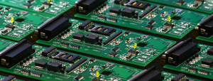
SMT PCB assembly manufacturer offers versatility in terms of Printed Circuit Boards. SMT or formally known as Surface Mount Technology is a fabrication and design process that tends to replace the through-hole mounting technique. It allows the placement of components of the Printed Circuit board directly on the board.
SMT technique is slightly newer than the through-hole method, but it has a standardized structure. Therefore, manufacturers tend to achieve uniformity in the components without much of a hassle. They offer high quality Printed Circuit Boards effortlessly.
To make the designing, developing and manufacturing process of Printed Circuit Boards easy, the Electron Device Engineering Council has set some standards and rules. Ever good manufacturer tends to follow these rules in order to come up with good quality Printed Circuit Boards.
Choosing SMT PCB for your device is the right choice. However, there are certain things that you need to know about this technology. In the course of this article, we will be discussing SMT technology in detail, its assembling procedure and the advantages it offers.
So, what are we waiting for? Let us get straight to the point
Table of Content
- Introduction to SMT PCB
- The assembly Process of SMT Printed Circuit Boards
- Importance of SMT PCB Assembly
- Summary
Introduction to SMT PCB
Initially, manufacturer of Printed Circuit Boards was a fan of through-hole technology. However, as the technology advanced, so did the methodologies of Printed Circuit Boards. It seems that SMT is the next level of through-hole technology.
Although SMT technology has been around for years, it was around the mid-80s when almost all PCB manufacturers started using it. Once they shifted from through-hole to SMT, they became a fan of all the advantages it offers.
In the early days, people named SMT technology as the Planar mounting technique. There were leads beneath and around the components and all components come with the surface-mount packages. To form a connection between the tracks and the components of Printed Circuit boards, there is no need for a drill.
To make direct contact with the components and the PADs, you will be needing component leads. Likewise, stencils are required to the placement of solder on an empty PDA. Finally, you would be placing the components on solder paste using a Pick and Place machine. Remember, the PADs need to be covered with the solder paste before the component placement takes place.
Once you are done with placing the components on the printed circuit board, you will then have to make it go through a reflow oven. There are several options for soldering the Printed Circuit Boards, but most of the time the manufacturer prefers the Vapor.
Importance of Surface Mounted Technology
SMT or Surface Mounted Technology tends to offer outstanding benefits. The Printed Circuit Board manufacturers are fully aware of its efficiency and effectiveness. There are several reasons, why modern manufacturers prefer SMTover other PCB techniques.
For instance, with SMT you can effortlessly achieve a higher level of density. Something, you might not be able to achieve with other Printed Circuit Board Technologies. Despite offering high processing power, SMT technology does not have an impact on the size of the PCB.
In fact, you can have a highly complex SMT PCB, yet it will be small and lightweight. Due to these reasons, SMT has become increasingly popular among the consumer electronics world. People now prefer having smaller and lightweight gadgets.
It is simply not possible to achieve the same results with orthodox technologies; therefore manufacturers are turning towards SMT technology.
The assembly Process of SMT Printed Circuit Boards
The assembling process of the Printed Circuit board might not seem exciting, but we do believe that having basic knowledge helps. Of course, when you plan to purchase an SMT PCB, you really need to know the basics in order to make the right decision.
Instead of going through the internet and reading several extremely technical articles. We have made your life easier by compiling everything into one article and that too, in a non-technical way. Below are the steps that take place behind closed doors.
There are four main stages of the Surface Mount Technology assembling process via the reflow method. Below, we have explained every stage in detail.
Stage I: Paste Application
See the steps below.
Printing Machine for Solder Pasting
First and foremost, you need to focus on solder paste placement in the SMT PCB assembly process. In case, you are wondering what is solder paste? It is a paste, grey in color, and compromise of different metals tiny particles. The most common metals used for soldering paste include silver, lead, and tin.
The solder paste tends to acts as a glue. With the help of this glue, you are able to stick the components to the Printed Circuit Board. Thus, ensuring the board will hold onto those components during the remaining stages.
PCB Stencil
Before applying the paste, you will have to place a Printed Circuit Board stencil on the bare board. A stencil has laser-cut wholes and it is a small stainless sheet. The PCB stencil makes it possible to apply a solder mask to those particular parts of the Printed Circuit Board, where you plan to place the components.
You will have to lock the PCB and the PCB stencil in an automate paste printer for the application of solder paste. To apply the precise amount, lead –free solder paste on the pad, the machine uses a squeegee.
After that, the machine smoothens the surface and spreads the paste evenly into the required areas by dragging a blade across the Printed Circuit Board stencil. Once, this step is completed, remove the stencil. You would see solder paste only on the desired areas.
SPI Machines
Studies show that about 70 percent of the SMT soldering problems are result of low-quality solder paste printing. Therefore, it is imperative to double-check where the solder paste printing is done in the correct manner. If you have a low volume PCB order, then using a good solder paste printing method would be sufficient.
However, if you plan to produce high volumes, it is imperative to use a Solder Paste Inspection (SPI) machine to prevent the extra cost that you would have to pay due to the rework. The modern SPI machines are efficient enough to determine even a minor problem with the soldering paste.
They come with high-resolution captures that have the ability to capture images in 3D. They use these images to assess the quality of solder paste based on different factors. Some of these factors include height, alignment, and volume.
SPI machine is able to identify a bad solder instantly and allows you to resolve the problem before it takes on a serious note. To add a more sophisticated touch to the monitoring process, modern manufacturers use the Automated Optimal inspection along with the SPI machine. Both these machines ensure timely identification of the problem, thus saving manufacturer money by avoiding a lot of rework.
In addition, both these machines tend to ensure the ofproduction and delivery ofsmooth and error-free Printed Circuit Boards.
Stage II: Placement of Component –Automatic
Here are the steps to place the component automatically.
Glue Dispensing Machine
Initially, you would have to apply dots of glue onto the board. For this purpose, the Glue dispensing machine is required. Later, you will place the components on these glue dots. The purpose of performing this step is to ensure that the components do not dislodge during the soldering phase of the contacts and leads.
This step is imperative for double-sided Printed boards or for wave soldering. As the force of the wave, the solder might dislodge the components leading to some serious issues in the manufacturing process. The glue tends to holds these components in place and prevents dislodgement.
Pick and Place Machine
Pick and Place machine acts as the backbone of the SMT PCB assembly. This sophisticated machine is responsible for picking up the components and placing them on the bare board. In the old days, this particular stage of PCB involved human hand.
People use to pick and place the components manually, but not anymore. Fortunately, modern Printed Circuit Board manufacturers have automated the step. They now have machines that deliver results that are more reliable and have the ability to 24/7.
The machine suctions up SMT components and places them rightly on the board. You feed the position of components into the machine, and it places them on the top of solder paste according to these positions. These machines are fast and efficient. They are capable of placing around 30,000 components every hour.
The Pick and Place machine place the components is a well-organized and efficient manner.
Stage III: Soldering
See the steps below.
Reflow Soldering Machine
Among the most common PCB soldering technique, we have reflow soldering. After completely populating the boards onto the components, you shift the board to a reflow soldering machine. The Printed Circuit boards have to go through several zones that have properly managed temperature system.
This ensures that the correct melting of the solder paste. In addition, it hardens steadily to form a strong electrical connection between the pads and their respective components.
Wave Soldering Machine
As the name suggests, a wave-soldering machine tends to evenly spread a molten solder paste over the solder components. To make sure that the solder adheres properly, the machine cleans the pads and the component contacts by applying a flux layer.
Next comes the preheating of the board and finally the tank of molten solder. Even though it is an effective method, but manufacturers today prefer the reflow soldering method.
Stage IV: Inspection
This is an important phase of the PCB assembly phase.
OAI: Automated Optical Inspection
After fully assembling the boards, it is time to inspect and test them. Manually inspection is no longer effective; therefore, you should opt for automated optical inspection. This type of inspection is extremely important due to the increased complexity of Printed Circuit Boards.
The modern OPI systems are efficient and effective. They have inbuilt cameras that take imagesof the board’s surface. They build these images in order to perform an indebt analysis. These machines also help in finding the in component and incorrect scratches and shorts.
In-Circuit Testing
In-Circuit Testing is among the most common techniques to checkwhether a fully populated Printed Circuit Board is working properly or not. You will need spring-loaded pins to perform the test. Each node of the Printed Circuit Board needs tocomes in contact with one of the pins.
After you place the board on the pins, press it. These test points will send test signals both in and out of the Printed Circuit Boards. Thus, allowing you to assess its performance in an effective manner.
Functional Validation Test
The last step is the Functional Validation Test. This decides whether the Printed Circuit Board is ready to be shipped or not. During this test, we are not mainly focusing on the physical aspect of the Printed Circuit Board. On the contrary, we will be testing the software loaded on them.
You tend to stimulate the environment in which the board is to perform via the Functional Validation Test. You cannot use a generic FVT for every type of Printed Circuit board. The test differs from one type of PCB to another.
Advantages of Surface Mounted Technology
Here are some advantages of SMT PCB assembly.
- You can effortlessly use both sides of the Printed Circuit Board without having to compromise on the efficiency and the robustness.
- The production process does not require a lot of time due to automated equipment.
- Surface Mounted Technology is less expensive in comparison to several other PCB technologies.
- You can incorporate more components on a single board because the SMT components are of a small size.
- SMT PCB offers complexity at a reasonable price.
- They are robustness and enhance the overall performance of the final product.
Read About: LED PCB Assembly
Summary
After reading the entire article, you do have the basic knowledge of how SMT PCB assembly works. KingPCB, offer the best PCB assembly services. Just drop in your design for a Printed Circuit Board and their technical team will ensure to deliver Printed Circuit Boards of the highest quality.
They are fully experienced in SMT PCB assembling. Their experience and expertise make them one of the best PCB manufacturers in the market. They promise to deliver only the best and will also be on time. Simply, reach out to them to resolve all your Printed Circuit Board issues.
